Shop By Category
Related Links
Whether it is a hand-drawn sketch, CAD, or a Solidworks file, our estimators are here to help. Contact us for a quote today!
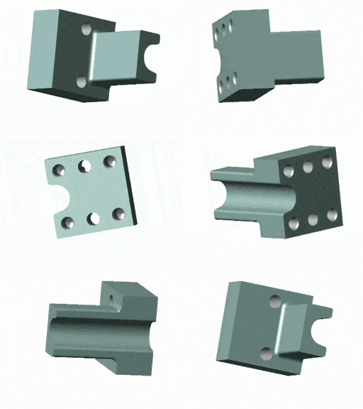
SolidWorks® is a computer-aided-design (CAD) software suite that creates 3D graphical representations of real-world parts and the tooling required to make them.
Email Us your design for a fast, detailed quote.
Planning & Design
Designing with SolidWorks® integrates all the knowledge needed to plan your hard tooling. Components interact with each other to ensure the perfect fit and functionality in 3D assembly. The tooling production can then be linked from the conceptual 3D models to prototyping and then the final production design.

Quality Control
Electronic design allows for 3D assembly. This provides a platform for ensuring parts fit together before they are made which helps to eliminate the trial and error phase in manufacture.
Efficient Production
Make parts knowing they will fit - this saves time and money. The solid model components can then be loaded through Mastercam® to our CNC mills. This suite of automation is how Punch Tools stays world-class and competitive with offshore competitors.
Data Transfer3D File Formats
2D File Formats
Ideally, supplying 3D Solid Models provides us with the most information, along with any accompanying 2D drawings. If 3D Solid Models are not available, 2D geometry files in CAD format are helpful. Where possible, it makes the process easier if files are kept in their native SolidWorks® format. |
EngineeringApplication Solutions Punch Tools tool and die manufacturing department looks after your metal stamping needs from simple perforate and shear to complex progressive tooling. We provide AutoCAD tool and die design services and have a team of experienced toolmakers and designers. Want to know whether metal stamping and machining can work for you? Just give us a call or email us.
Trust Punch Tools tool and die manufacturing facility to deliver your next tooling project! |

ABOUT US
OUR SERVICES
TOOL & DIE MFG
OUR PRODUCTS
INDUSTRY LIBRARY
11-211 Schoolhouse Street
Coquitlam, BC, Canada. V3K4X9
Telephone
604-521-6444
1-800-668-4996

